Trials and Tribulations of a 3D Printer

Made a blue today.

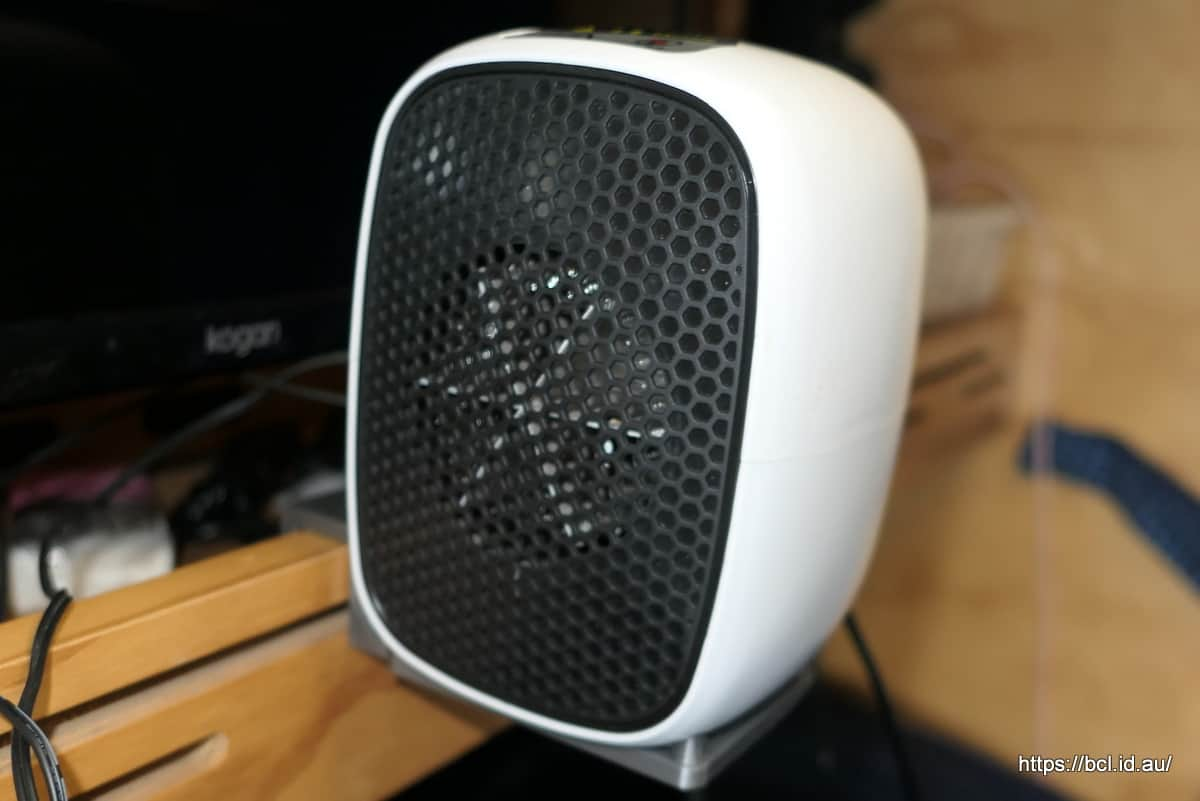
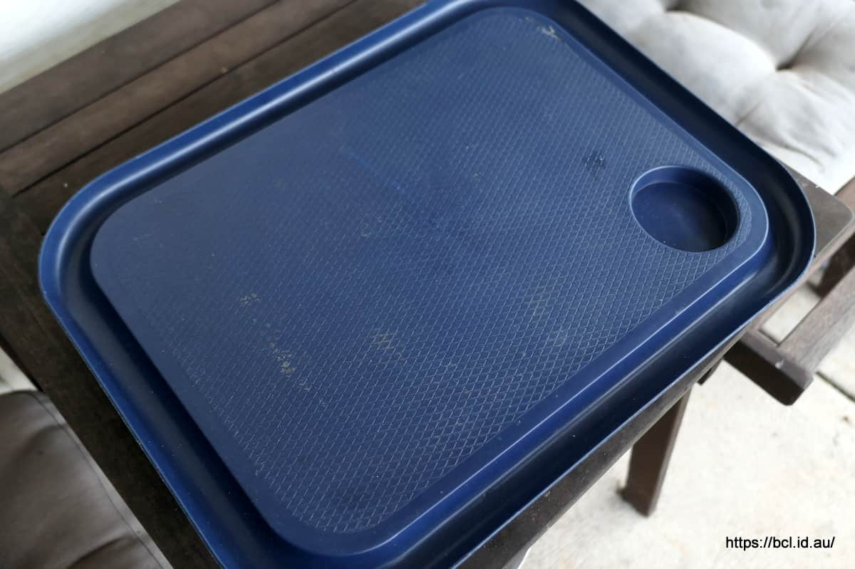
A while back I thought that my camper needed somewhere to store a stable table that I use in the cabin. I am not sure what they are called in the UK but they are a tray with polystyrene beads in the base to sit on your lap. Like this:

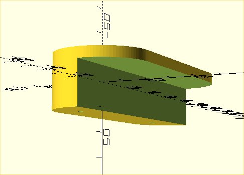
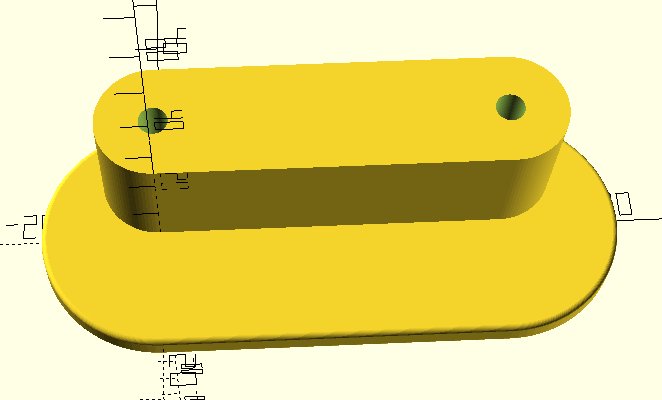
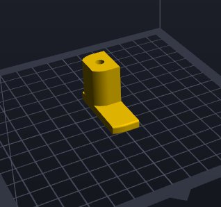
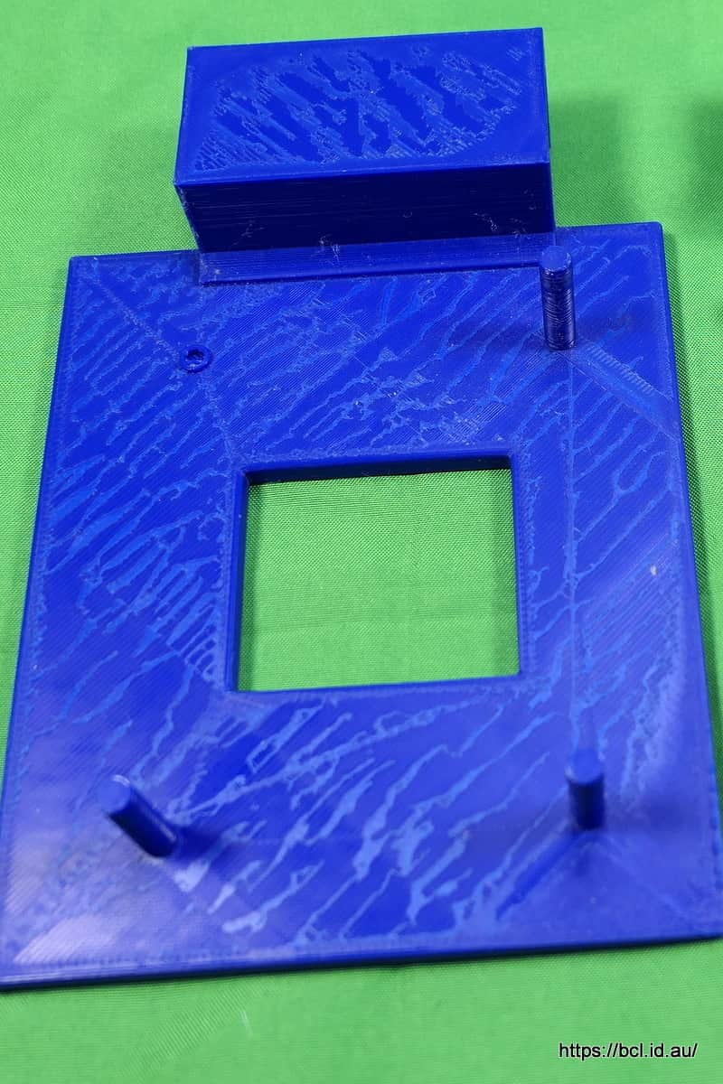
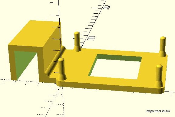
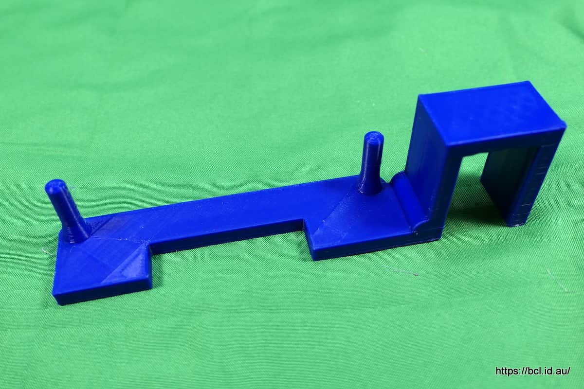
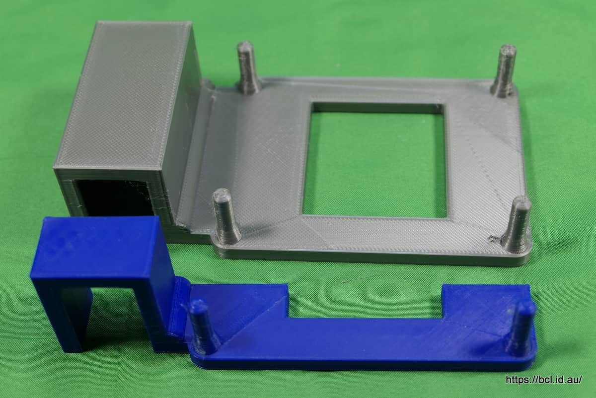
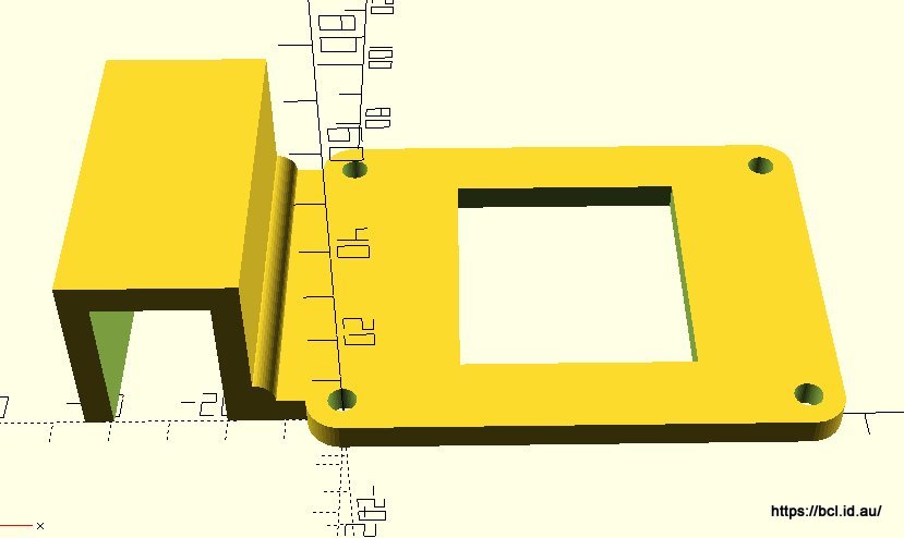
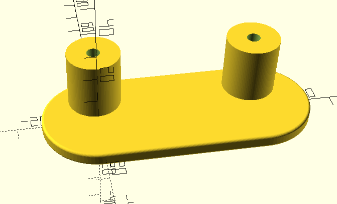
I designed a bracket that would hold one under the shelf (needs two brackets) and printed a small prototype - I always do this if there is fit criteria - just a small piece of the whole to test the design and fit. It looked fine.

Loaded the whole thing into the slicing software (transforms the CAD design into instructions for the printer) and found it didn’t fit on the bed, it was a tiny bit too large. Experimented with the transform and scaled it to fit. Then I made my first mistake I transferred the sliced file to the machine but didn’t print it. This all happened months ago.

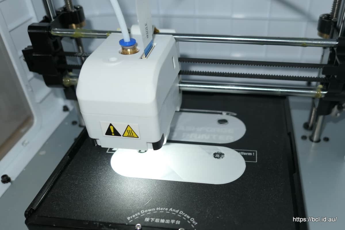
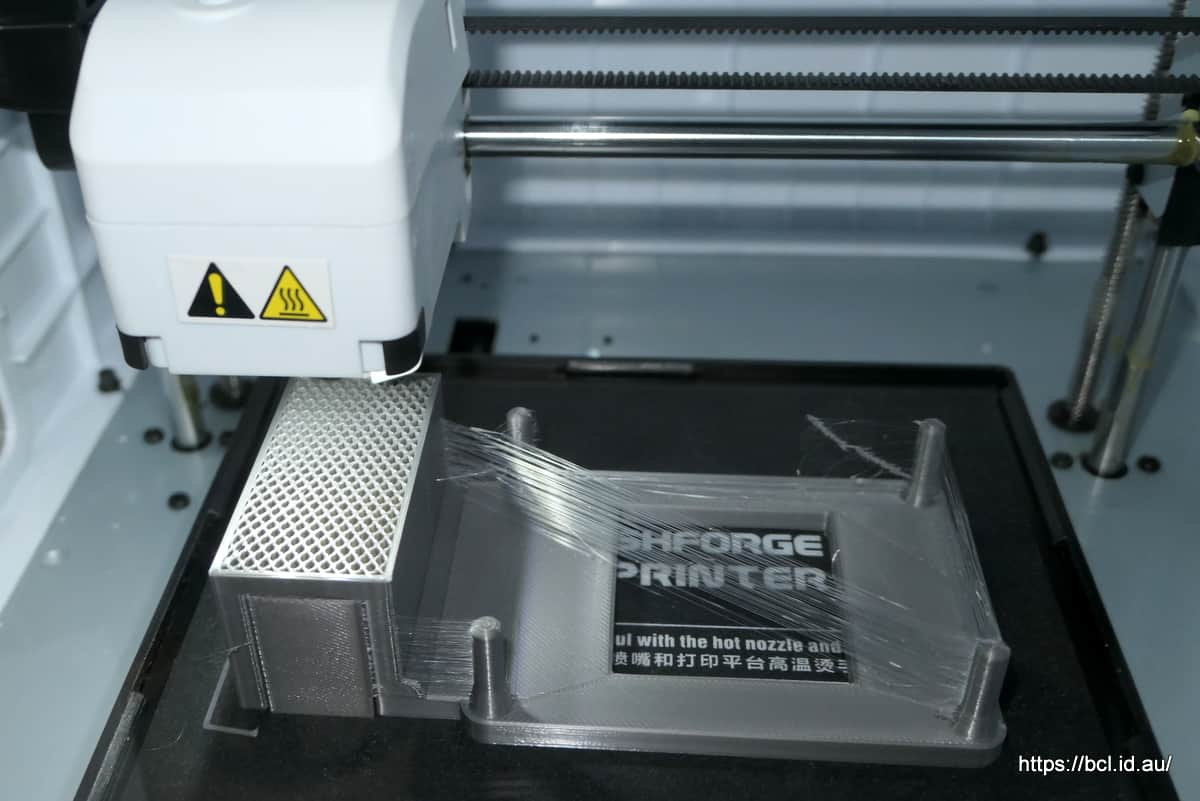
Anyway today was another wet miserable day and I was messing about in the car port with my camper when I remembered the idea for the bracket. Looked at the printer, there was the file so I set if off printing forgetting the details.

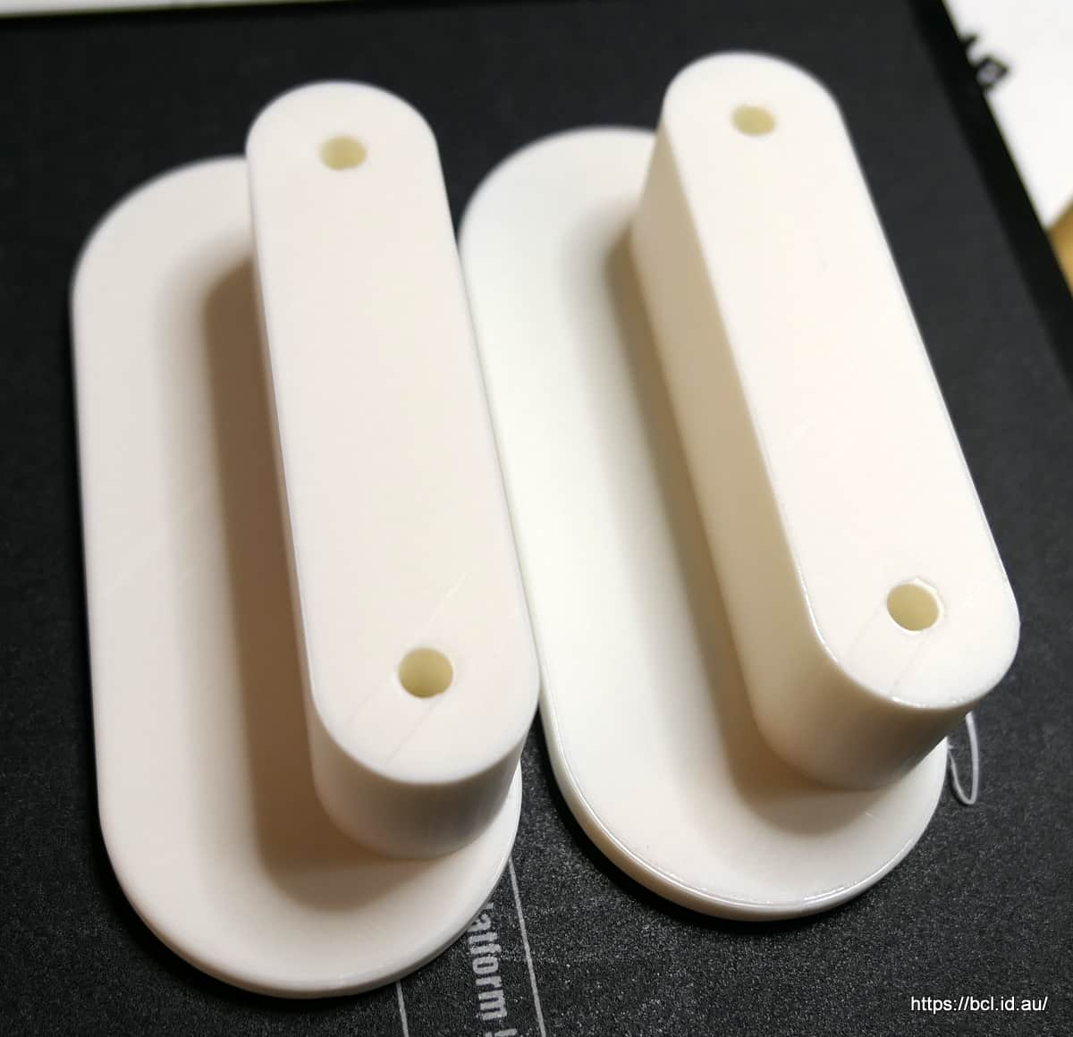
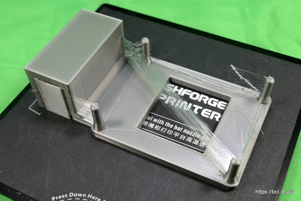
Four hours later I took the finished product out of the machine - why it took so long is another part of the tragic tale.

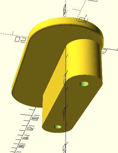
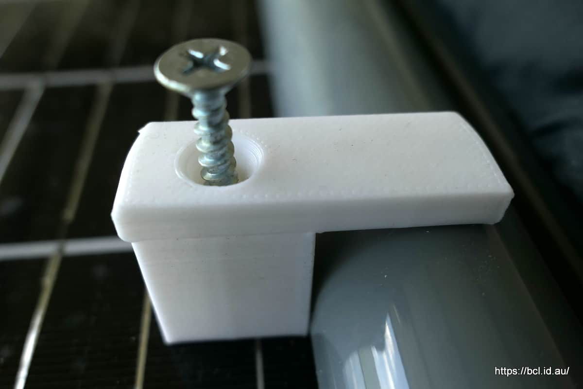
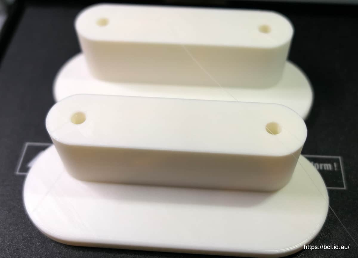
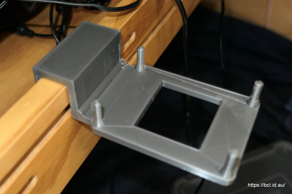
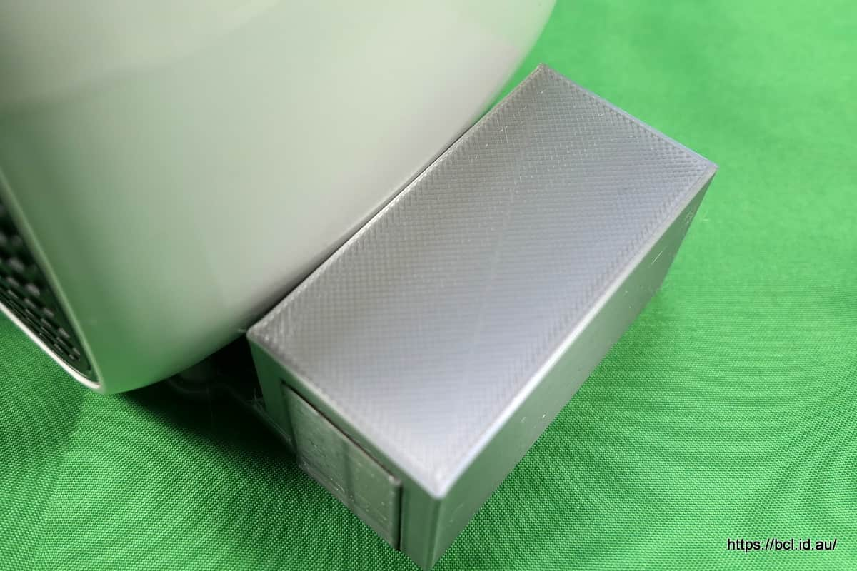
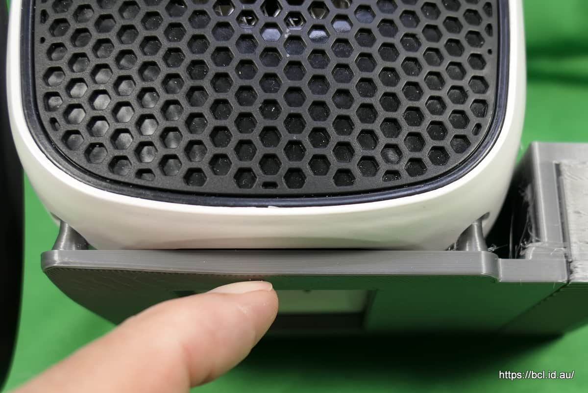
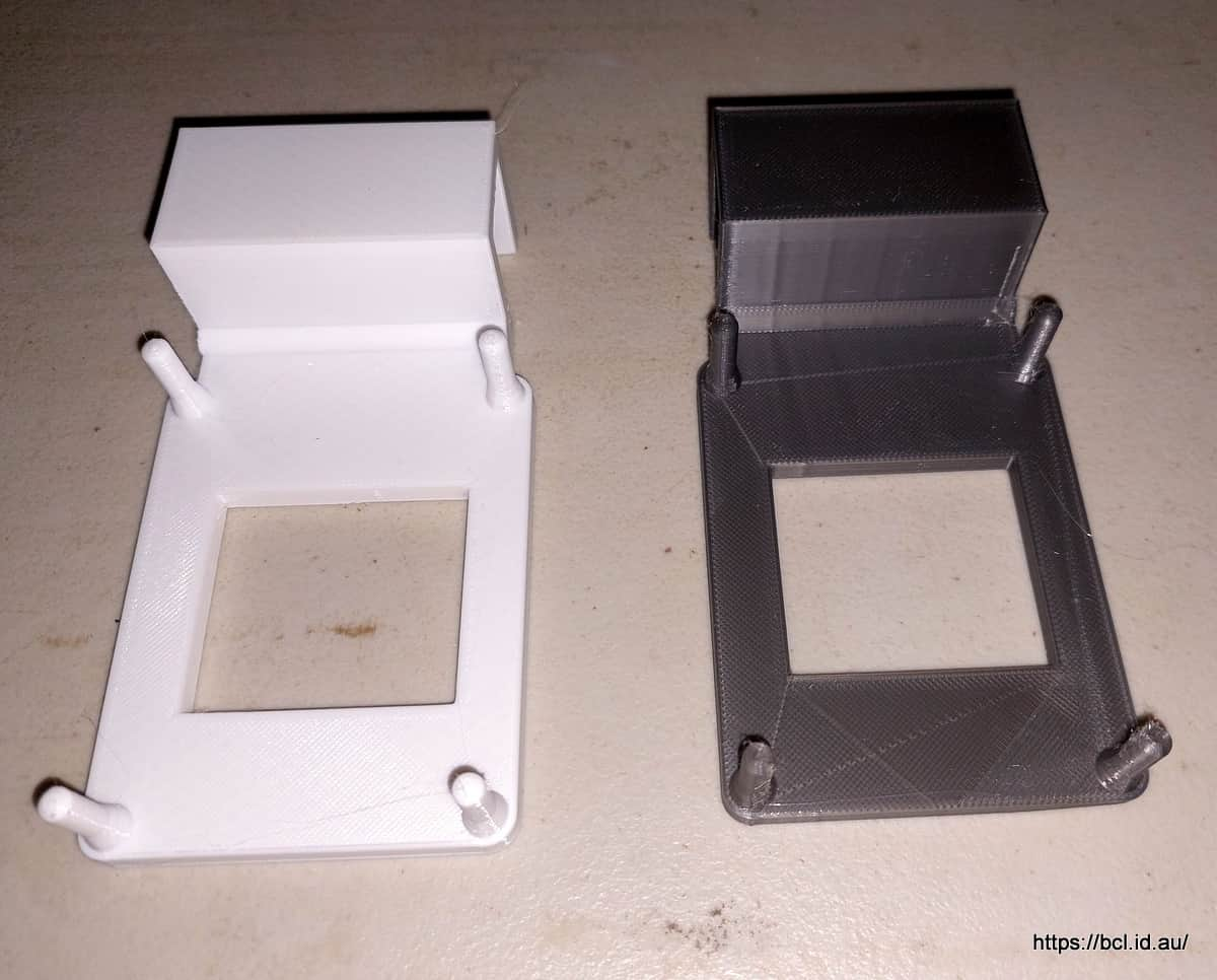
Of course the damn thing didn’t fit! it was about 1 to 2 mm too low - you’d have had a lot of trouble getting the tray in.
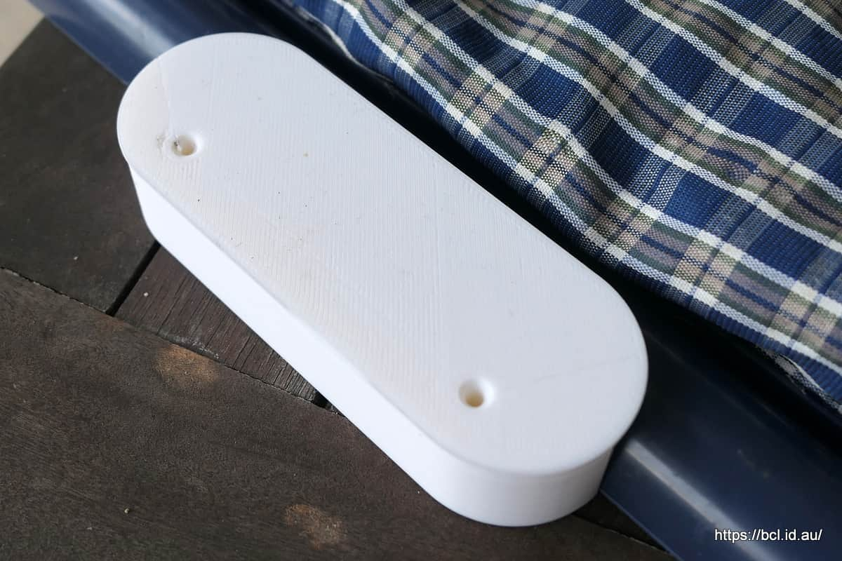
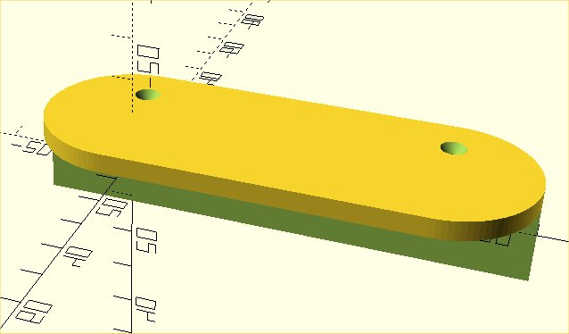
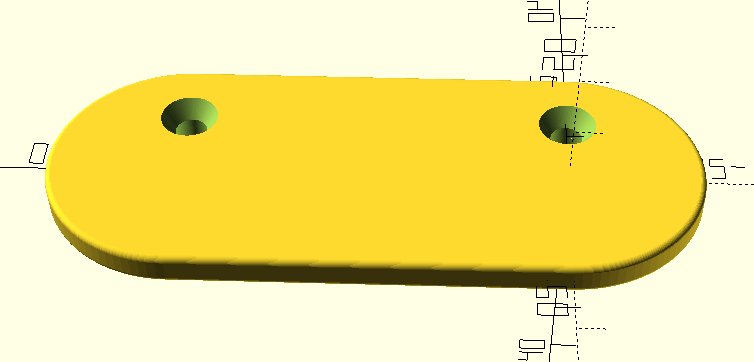
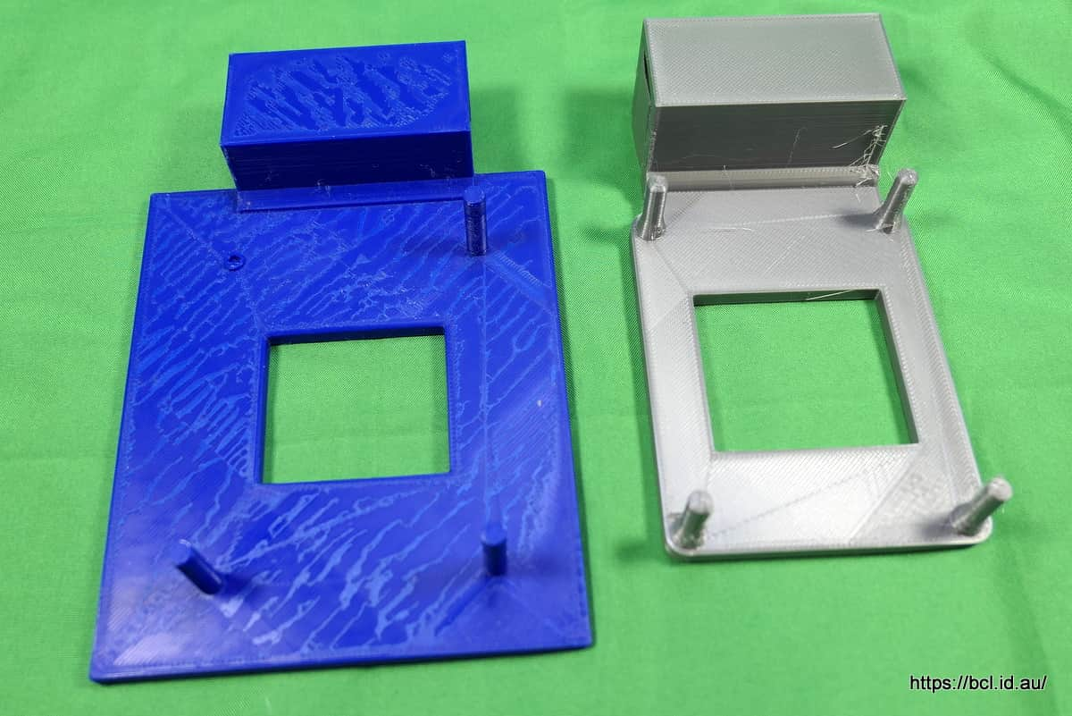
The screw holes had shrunk too :frowning_face:

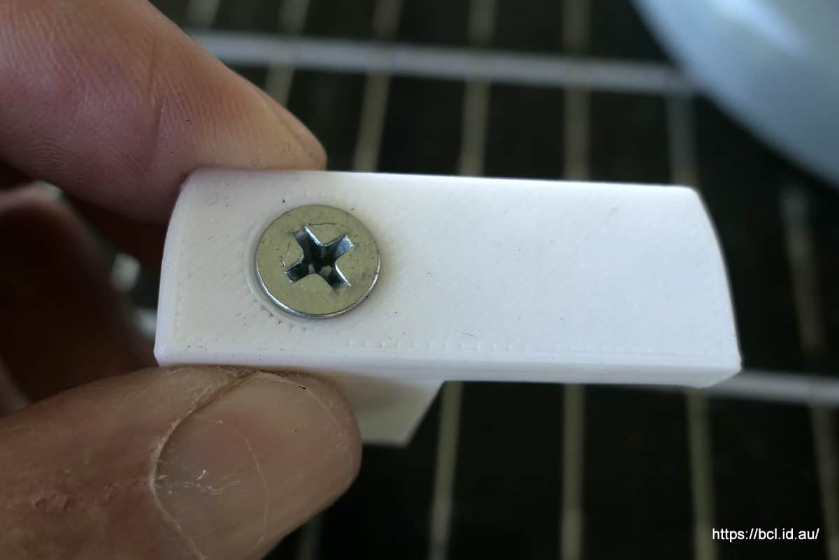
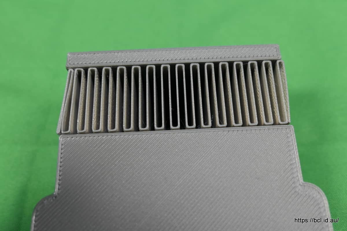
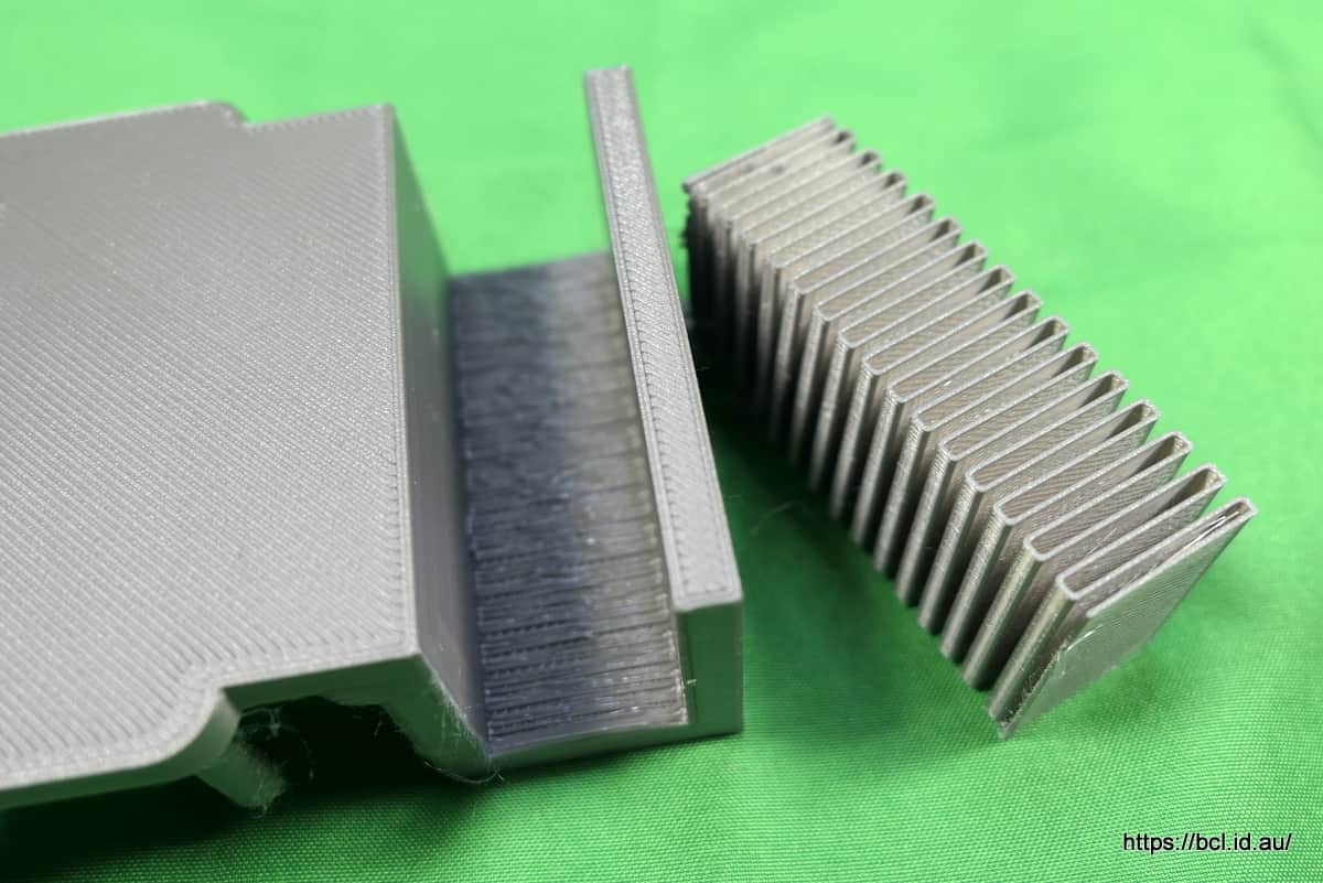
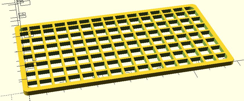
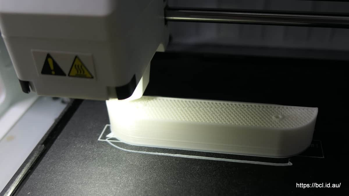
The reason it took so long to print was, that, for reasons I don’t remember, the fill was set to 70% whereas less than 50% would have been fine. You can just about see the close fill pattern here.

I was very peeved with myself. Now I am in two minds about just adjusting the length measurement to the full size model so it fits on the printer bed (easy fix) or redesigning it (I have a different idea for it)

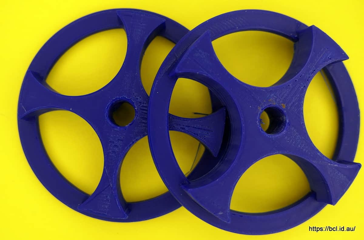
Wasted day - though I do have a prototype of something else printing now.

1 Like

This was the original design for the bracket made in OpenSCAD.

tray2

tray1

Because of the overhang it is printed upside down.

This is the really short bit of code required:

//Tray Holder

//Variables


lipthk=3; //top lip thickness
lipdp=20;  // depth of tray
hldthk=20; // Width of holder
scrdia=3;  // screew diameter
lth=60;  //length of device (centres)

//end Variables

$fn=100;

difference(){
    hull(){
        cylinder(h=lipthk+hldthk,r=hldthk,center=true );  
        translate([lth,0,0]){
            cylinder(h=lipthk+hldthk,r=hldthk,center=true); 
            }    
        } 
      //cutout
        translate([-hldthk-lipthk/2,0,-((hldthk/2)-lipthk)]){  
    cube([lth+(hldthk*2)+lipthk,hldthk,lipdp],center=false);  
      }  
      //holes
      translate([0,-hldthk/2,0]){
      cylinder(h=lipthk*2+hldthk,r=scrdia,center=true ); 
  }
      translate([lth,-hldthk/2,0]){
      cylinder(h=lipthk*2+hldthk,r=scrdia,center=true );
  }
  
  //chamfer for screw
  translate([0,-hldthk/2,-(hldthk+1)/2]){
    cylinder(h=scrdia+1, r1=scrdia*2,r2=scrdia,center=true);
  }
  
   translate([lth,-hldthk/2,-(hldthk+1)/2]){
    cylinder(h=scrdia+1, r1=scrdia*2,r2=scrdia,center=true);
  }
}

I am still very much a beginner in OpenSCAD but it is amazing what you can do with very few commands.

BTW the “lth” is the only one that needs to be changed.

The word that causes me the most trouble is “center” of course I spell it “centre” so the program thinks it is a variable that hasn’t been defined - a trap I fall into every time!

I can tell by the excitement generated by this thread that you want more…

A little project I knocked up yesterday to help overcome the disappointment of yesterday’s print is a spool holder that I plan to mount in my electric drill to wind wire and string from larger spools.

It only took about half an hour to write the script to produce this (including correcting all my syntax errors :cry: )

Obviously two are needed.

Wisely :smile: I printed a test version which came out like this (chopped down just to test the fit)

It’s a bit dirty because I took it down the garage to test whether the threaded rod fits correctly. As it happens it fits too well so I will add .5mm to the hole size - it’s a quarter inch threaded rod left over from a camera mount I made, translating it into metric was probably too accurate.

The other thing I realised was that the cut down version would do the job, no need for it to be as big as I originally envisaged.

One of the advantages of using variables in the script is that you only have to change things in one place to affect everything, this is the original script:

//500gm Spool Holder

//Variables

spdia = 52;  //500gm spool centre diameter
hldia = 6.5; //quarter inch threaded rd
spwdth = 50;  //width 500gm spool hole
rmwdth = 2; //thickness of lip
//end varialble

$fn=100;

difference(){
//body
cylinder(spwdth/3,d1=spdia,d2=spdia-1,center=true);

//hole
cylinder(h=spwdth,d=hldia,center=true);
    
//cutout

translate([spdia/2.5,0,0]) cylinder(spdia,d=spdia/2,center =true);    
translate([-spdia/2.5,0,0]) cylinder(spdia,d=spdia/2,center =true);        
translate([0,spdia/2.5,0]) cylinder(spdia,d=spdia/2,center =true);   
translate([0,-spdia/2.5,0]) cylinder(spdia,d=spdia/2,center =true);       
}
translate([0,0,-((spwdth/3)/2)+(rmwdth/2)]){
difference(){
  cylinder(rmwdth,d=spdia+5,center=true);  
  cylinder(rmwdth+2,d=spdia-5,center=true);    
}
}

Does life get anymore exciting that that? :icon_wink:

Another scintillating day in the 3D Printer department.

As as mentioned earlier I redesigned the tray holder to something I hope is a bit less clunky.

New Tray 1

New Tray 2

The new dimensions were plugged in then a tiny section printed which would demonstrate that the screw fitted OK and that the lip fitted comfortably over the tray.

New Tray Slice

This was only a 30 minute print so I soon had a sample to test.

I wanted the screw head to sit a little lower but otherwise it was fine.

I made a slight adjustment to the screw head hole and now there are two brackets printing out as I type.

This is the code to produce this “thing” in OpenSCAD

//New Tray Holder

//Variables

tpwd=40;     //top width
tpthk=5;     //top thickness
tplth=60; //top length (centres)

bsht=22;     //base height needed to hold tray
bswd=tpwd/2;      //base width (might proportion of top??)

scdia= 5;    //screw diameter (8g = 4.3 by 38mm
schddia=9.5;      //screwhead dia (8.8mm)(increased by .5)
schdht=4.5;      //screwhead height (increased by .5)

mhsp=1;      //minkowski sphere

//End Variables
$fn=100;
// top
difference(){
    union(){
minkowski (){
    hull(){
     translate([0,0,0]) cylinder(h=tpthk-mhsp*2,r=tpwd/2,center=true) ;  
        
    translate([tplth,0,0]) cylinder(h=tpthk-mhsp*2,r=tpwd/2,center=true)   ;  
    }
    sphere(r=mhsp,$fn=40);
}

//Base

translate([0,(tpwd/2)-(bswd/2),(bsht/2)+(tpthk/2)]){
hull(){
     translate([0,0,0]) cylinder(h=bsht,r=bswd/2,center=true) ; 
    translate([tplth,0,0]) cylinder(h=bsht,r=bswd/2,center=true) ; 
}
}
}
//screwhole
translate([0,bswd/2,bsht/4]) cylinder(h=bsht*2,d=scdia,center=true);
translate([tplth,bswd/2,bsht/4]) cylinder(h=bsht*2,d=scdia,center=true);

//Screwhead

translate([0,(tpwd/2)-(bswd/2),-(tpthk/2)+(schdht/2)]) cylinder(h=schdht,d1=schddia  ,d2=scdia, center=true);
translate([tplth,(tpwd/2)-(bswd/2),-(tpthk/2)+(schdht/2)]) cylinder(h=schdht,d1=schddia  ,d2=scdia, center=true);
}

Here they are, hot off the press after 9 hours printing.

Sorry about the quality of pic but it is late and dark.

Well done.
Time well spent

1 Like

Printed out the final version of the spool holder today, only took about 1.5 hours to print, as suggested earlier I made it less thick than the original design, enlarged the central hole and the spool holder part. Used the end of a roll to print it too.

It is a perfect fit with no play and the 1/4" threaded bar pushes in OK, perhaps could have been 0.1mm larger but this is fine. Quite pleased.

The photo is of them straight out of the printer before tidying up.

Genius … meanwhile I spent 1.5 hours less productively :sweat_smile:

1 Like

I have a very small 500watt heater for my camper, on very cold nights it only needs to be run for a few minutes to warm the whole living space up. The problem is that there is really nowhere to safely run it - it really can’t sit on the bedding nor is there a space on the shelf.

Ages ago I made a little platform for it on my three D printer:

It was one of the first things I made but it worked - however as you can see one of the pins broke and it was far too large, the actual standing base of the heater was within the area of the pins. So it was time for a redesign and a strengthening of the pins, this is what I came up with:

Camper Heater Holder Pins

I printed a portion just to check the fit:

As it happened it was a good job I did because the “Hook” part interfered with the side of the heater so I had to move it 5mm away. Now was the time to print the real thing.

Here it is hot of the press:

All those fine filaments would drive a model maker up the wall but they don’t worry me I just trim them off with a knife.

Here is the new one compared to the old:

BTW the hole is needed because the switch is in the centre of the base of the heater and the size is to allow for the heater to be stood either way.

Because the “Hook” is a large unsupported plane supports have to be printed otherwise it would just collapse while the plastic was still molten - they are easily removed

How does it fit?

BTW here you can see the difference between the sample piece and the final, notice how much further the pins are from the “hook”

The heater fits perfectly

It took about five hours to print, this is the Openscad code

//Stand for Camper Heater

//Variables

edge_d=20;      //distance of pins from heater side/front
wide_d=79.7;    //Separation of pin centres width
len_d=59.8;     //Separation of pin centres length
wood=19.5;        //Thickness of wood
pin_d=5;        //Diameter of pins
pin_h=15;        //Pin Height (reduced from 20)
thk=5;          //Material thickness
mink=1;         //minkowski number
hole_w=39.5;      //hole for switch
hole_l=44;      //hole for switch

//End Variables

$fn=50;
//Base

difference(){
hull(){
    translate([0,0,0])cylinder(h=thk, d=pin_d*2);
    translate([wide_d,0,0])cylinder(h=thk, d=pin_d*2);
    translate([0,len_d,0])cylinder(h=thk, d=pin_d*2);
    translate([wide_d,len_d,0])cylinder(h=thk, d=pin_d*2);
}

//Hole for switch    
    translate([wide_d/2-hole_w/2,len_d/2-hole_l/2,-1])        cube([hole_w+mink*2,hole_l+mink*2, thk+mink*2]);
  
}

//Pins


//Four Mounting Pins (good placement)
translate([0,0,0])pins();
translate([wide_d,0,0])pins();
translate([0,len_d,0])pins();
translate([wide_d,len_d,0])pins();

//Hook

translate([-wood-edge_d-thk,0,0])hook();

//fill gap

translate([-(edge_d/2)-thk-1,0,0]) cube([edge_d,len_d,thk]);

//Fillet
translate([-edge_d/2-thk,0,thk]) rotate([-90,0,0])cylinder(h=len_d,d=thk*1.5);

module pins(){

    cylinder(h=pin_h+thk+mink*2,d=pin_d,center=false);
//Broaden base of pin    
    cylinder(h=thk*2,d1=pin_d*2,d2=pin_d);
//Round top of pin   
    translate([0,0,pin_h+thk+mink*2]) scale([1,1,.5])sphere(d=pin_d);
}  
module hook(){
      difference(){
        cube([wood+thk*2,len_d,wood*1.4+thk]);
          
        translate([thk,-1,-1]){
          cube( [wood,len_d+2,wood*1.4+1]);  
        }
      }
  }

BTW the pins fit into screw recesses in the base, they keep it firmly in place.

However if the new pins prove to not be up to the task I have a model with holes for 4mm bolts waiting in the wings.

I hope that was a little bit interesting.

1 Like

It’s certainly very impressive Bruce!

I’m impressed too. You are the one to turn to when you need “something” but you’re not sure what, and they don’t sell it in the shops. Bravo👍

Just as a practice in OpenScad made a slight design change to make the tray holder lighter. Have not printed this out.

image

Made another heater mount

Why? I hear you ask…

The original one on the right is PLA, a plastic made from something like corn flower starch, it is great for most purposes but it does have faults, one of them is its lack of resistance to UV (sunlight) and a fairly low melting point. Obviously one could paint it to protect it from UV.

The new one on the left is PET which is the same plastic that your drinking bottle is made from, it has several advantages, higher melting point, UV resistance and also doesn’t leech, so safe for things where human consumption is involved (not a worry in this application) I think it might be stronger than PLA though that is not a concern as PLA is plenty strong enough for most purposes.

It will be interesting to see how they fare in actual use though I think the PET is obviously more suitable for this particular purpose.

I agree :+1:

Needed a grid for my air dryer. Designed one in Openscad.

The Openscad code that you have all been waiting for.

//Drying rack for Filement Dryer

//Variables----------

wide=68;
lgth=130;
thk=3;
crnr=3;
edge=3;


//Grid variables
grid=7;

//End Varaiables

$fn=60;

//Base Shape

difference(){
    hull(){
        translate([0,0,0])cylinder(h=thk,r=crnr);
        
        translate([lgth-(crnr*2),0,0])cylinder(h=thk,r=crnr);
        
        translate([0,wide-(crnr*2),0])cylinder(h=thk,r=crnr);
        
        translate([lgth-(crnr*2),wide-(crnr*2),0])cylinder(h=thk,r=crnr);
            
        }    
    hull(){
        translate([edge,edge,-1])cylinder(h=thk+2,r=crnr);
        
        translate([lgth-(crnr*2)-edge,edge,-1])cylinder(h=thk+2,r=crnr);
        
        translate([edge,wide-(crnr*2)-edge,-1])cylinder(h=thk+2,r=crnr);
        
        translate([lgth-(crnr*2)-edge,wide-(crnr*2)-edge,-1])cylinder(h=thk+2,r=crnr);
            
        }  
}
//grid

translate([-crnr/2,-crnr/2,0]){  
    difference(){
      
        cube([lgth-edge,wide-edge,thk],center=false)  ;
        
        for ( i=[0:grid+(thk/2):lgth+grid]) {
        for ( j=[0:grid+(thk/2):wide+grid]) {
            translate([i,j,-1])
            cube(grid,center=false);
        }}
    }
}

It printed out quite nicely in PLA and fitted perfectly

1 Like